Steps to Build a Layout

Step1

Step 2

Step 3
Step 4
Step 5

Step 6
Step 7

Step 8
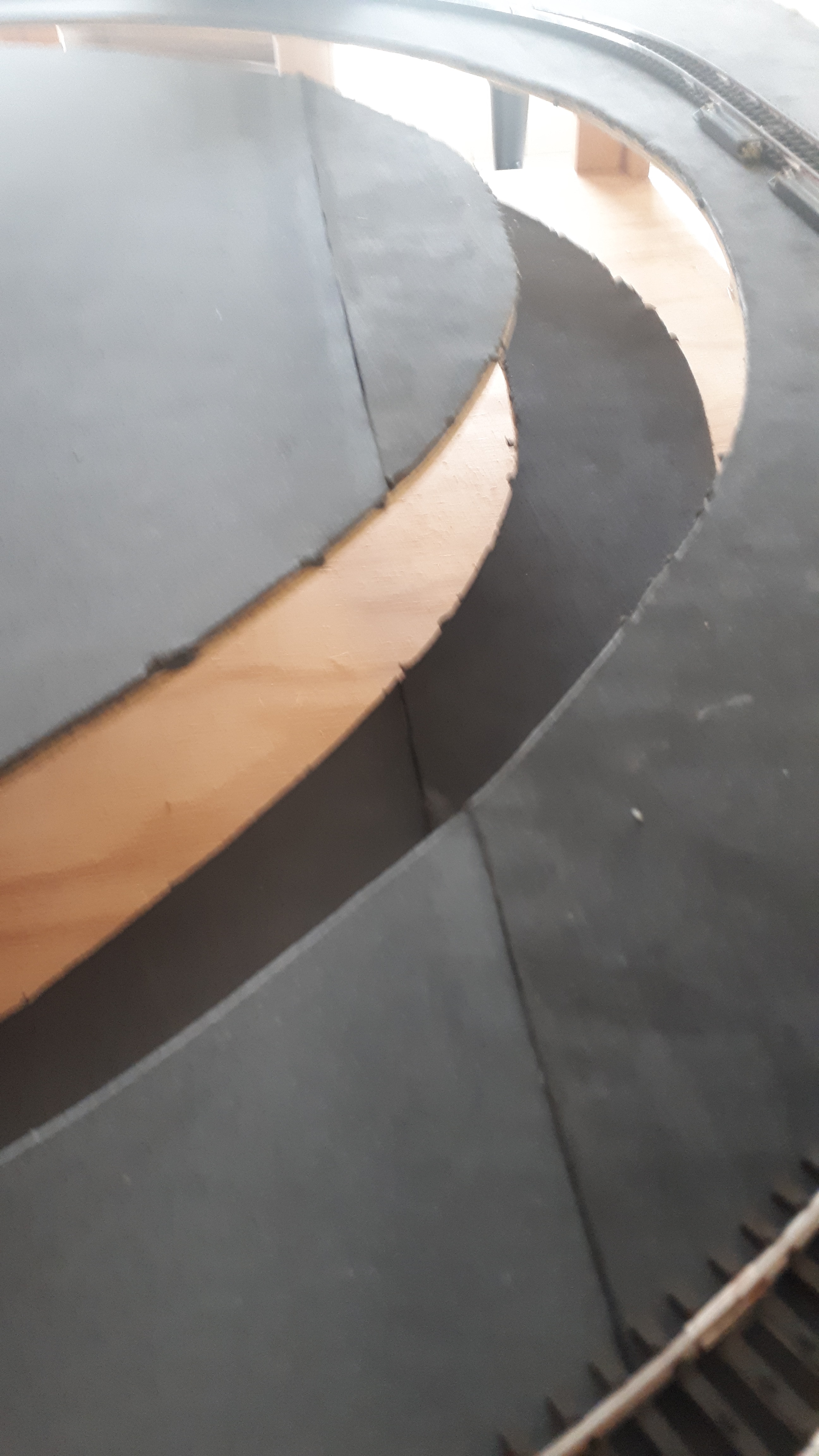
The board with the attached gradient sections is now covered with a 3 mm rubber sheet that has double-sided glue on the side that goes onto the board. The rubber is used to deaden the running noise of the trains as an alternative to cork. It also provides an excellent surface for modelling all of the scenery equipment, for example; buildings, trees, grass, lights, and roads, etc. Strips of 3 mm x 30 mm rubber can be used for laying beneath the tracks instead of covering the whole board with the rubber sheet—if so desired.

Step 9
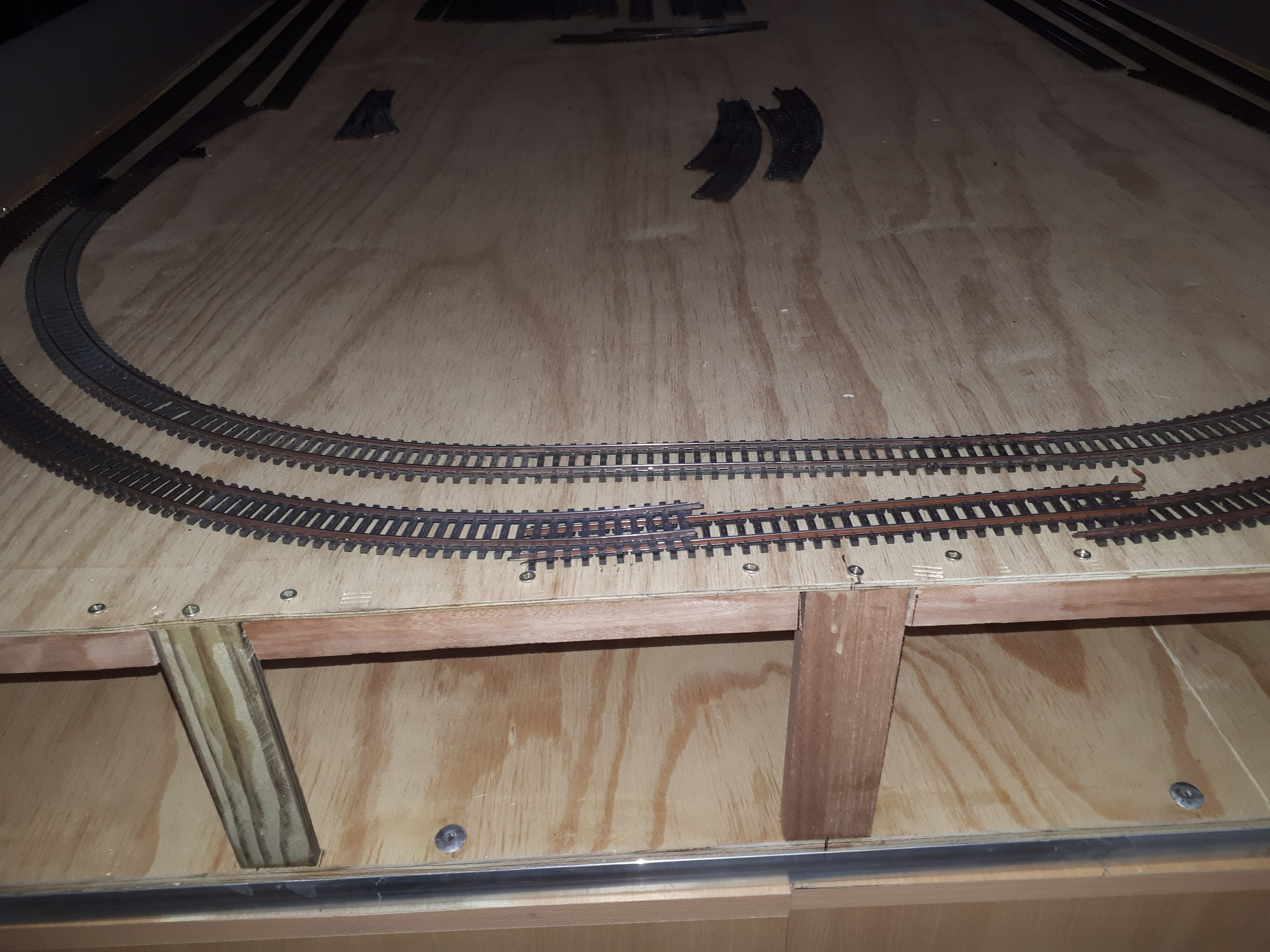
The layout board is displayed here with the rubber sheeting. The elevated track sections are now supported by the correct sized wooden supports. The ideal gradient is 4 %. These sections have not yet been covered with the rubber sheeting.
Step 10
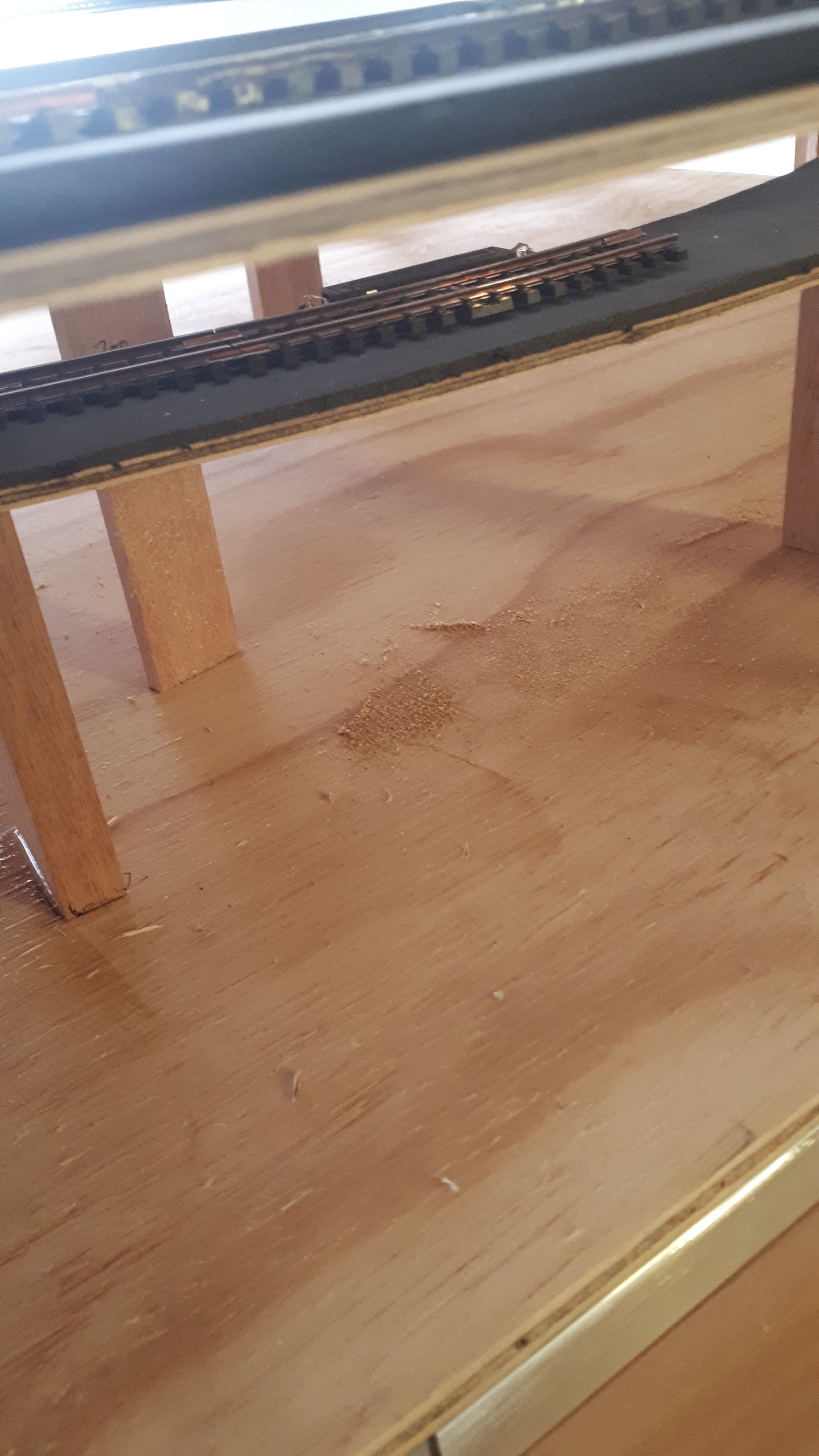
Step 11
The support pillars for the different levels.
Step 12
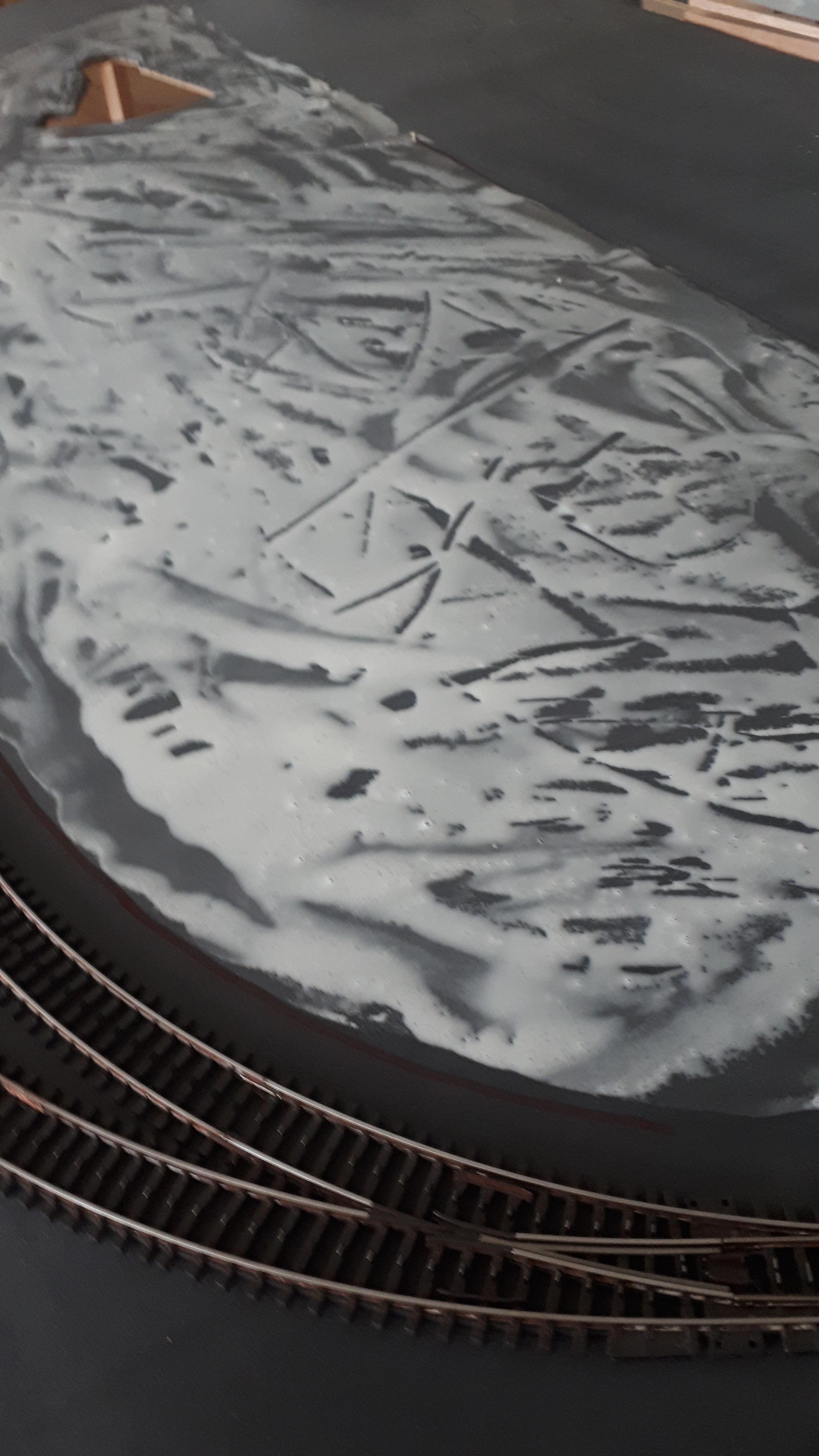
The first step in the scenery building. The rubber sheeting is covered with a mixture of 50% wood glue, 50% water, and a few drops of dishwashing liquid. The soap assists the glue mixture with spreading.

Step 13
The ground cover is sprinkled onto the glue where the locomotive yard will be. When the glue is wet, the ground cover will look like a disaster, that is until the glue is dried.

Step 14

Step 15

Step 16

Step 17
Step 18
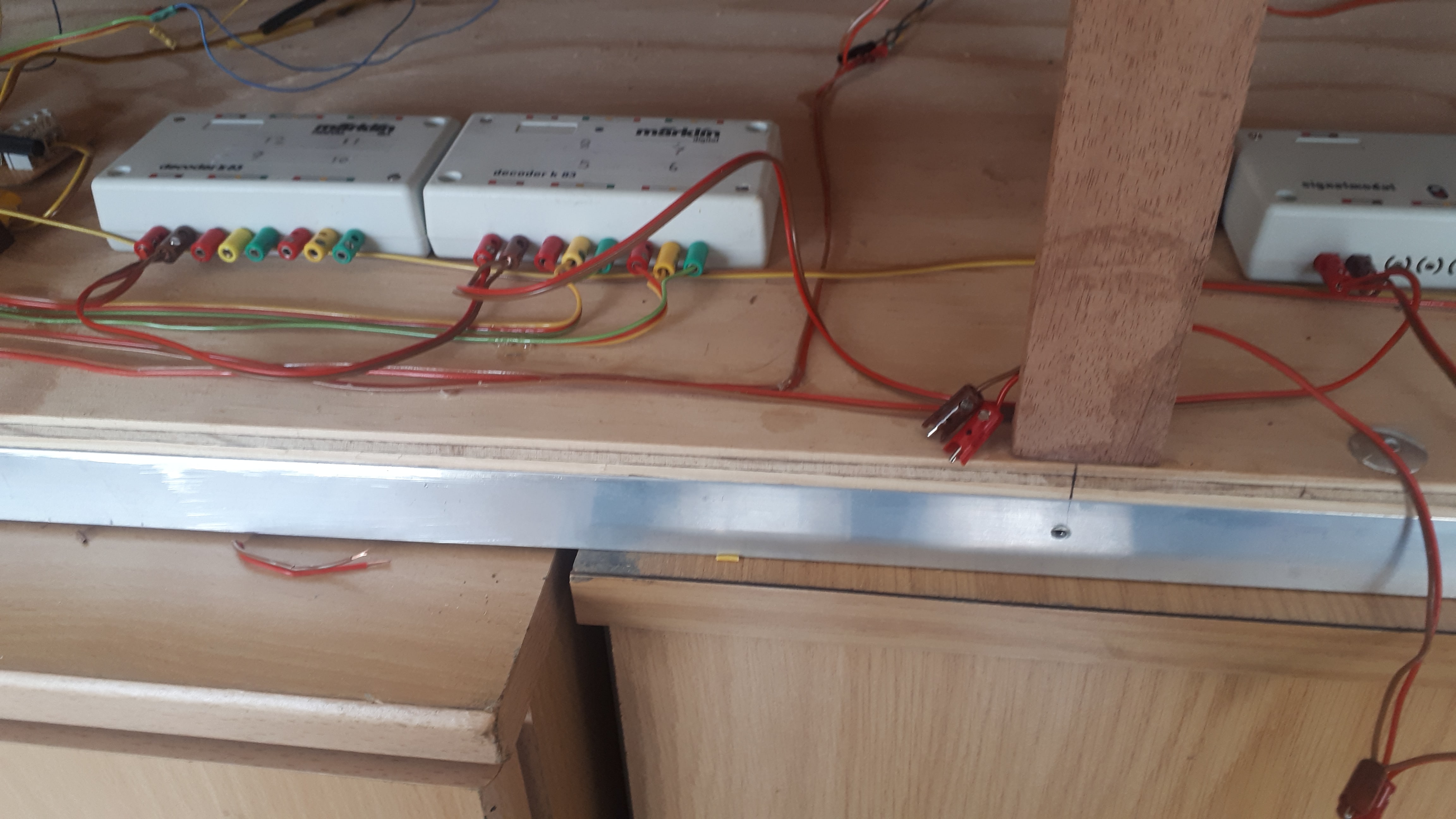
When connecting up all of the wires, lay them out neatly. Should a fault occur later on, it will be easy to trace the wiring back to the fault or broken electrical item.

Step 19
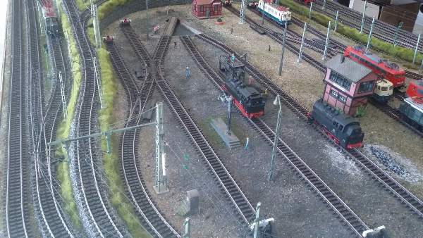
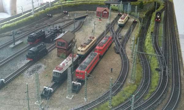
The time has arrived for the locomotives to go onto the layout and the trains are given their first run on the layout. The check is now done for dirty tracks, sticky turnouts, and hopefully no derailments.

Step 20
The ballast is now applied to the track using the Proses Ballast Applicator. The ballast is glued into position on the tracks preferably using a 50% latex glue, 50% water, and a few drops of dishwashing liquid mixture. Since latex glue is rubber-based, the trains run quieter than the alternative, which is wood glue. A dropper should be used to apply the glue. This helps to prevent the glue from getting onto the tracks, turnout moving parts and power contacts. If the glue is spilt onto these parts, clean it off immediately. If you do not, you are in for a frustrating time when you start running your trains.

Step 21

Step 22

Step 23
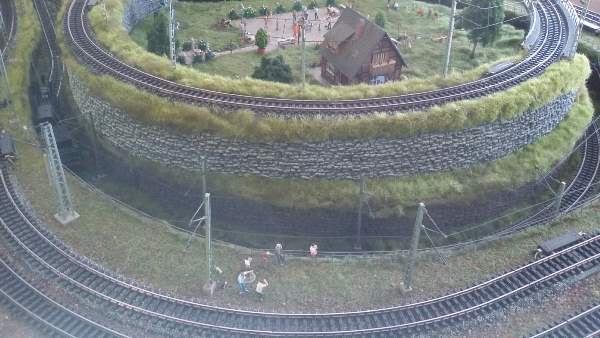
The layout is now complete
Contact Miniature Railways
Quick Links
- Home
- Gallery
- Our Range
- New Models and Releases
- Contact and Conditions
- Privacy Policy
Social Media
Contact Details
steve@minirail.co.za
082 558 3531
010 237 0052
Miniature Railways
Farrarmere
Office Hours
Monday - Friday: 08:00 - 17:00
Saturday: 10:00 - 14:00
Sunday: Closed
You are most welcome to visit me. Please contact me beforehand to set up a time.